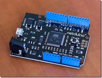
Some time ago I wrote about FEZ Mini and FEZ Domino – first affordable development boards for .NET Micro Framework. Today I’m excited to tell you about another device called Netduino. Similar to FEZ Domino this board is pin compatible with Arduino, and therefore most of Arduino shields should work fine on Netduino. This makes transitioning your project quite easy. Only care should be taken to ensure that shield can run at 3.3V logic levels (because Arduino runs at 5V).
Of course Netduino is much more powerful than Arduino, thanks to Atmel 32-bit microcontroller running at 48Mhz, 128KB flash for code, and 60KB of RAM. What’s more, this is a first truly open source .NET MF device, meaning that you can modify and compile the source code of its firmware yourself. You will find more information and rapidly growing community of Netduino users at http://www.netduino.com/. I got mine yesterday and it looks great. But enough said about Netduino – lets put it to some good use.
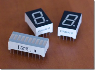
You can find few introduction videos at http://www.netduino.com/projects/ to get you up and running with hardware and software configuration so I won’t repeat it here. The first tutorial shows you how to blink a single onboard LED, and it would be easy to do the same with more LEDs – you can simply wire them to all other digital I/O pins of the board. But instead of single LEDs you might want to use some other LED components, such as 10-segment LED bar graph or 7-segment display, and it will work the same way.
Netduino has 14 digital pins, and 6 analog pins that can be used as digital as well. But even with simple displays shown above we will quickly run out of available pins. In this tutorial I will demonstrate how you can use shift registers to extend the number of digital output pins available on the device.
Shift registers are very simple ICs, and one popular chip is 74HC595. It’s referred as 8-bit serial to parallel converter. It requires only three lines connected to the microcontroller (data, click, and latch) to get 8 outputs. But what’s cool is that you can connect more than one of such chips in series in case you need more outputs. You can learn all about shift registers from this Arduino tutorial so I won’t repeat it here, and I’ll only show how to use them with .NET Micro Framework devices.
Hardware setup
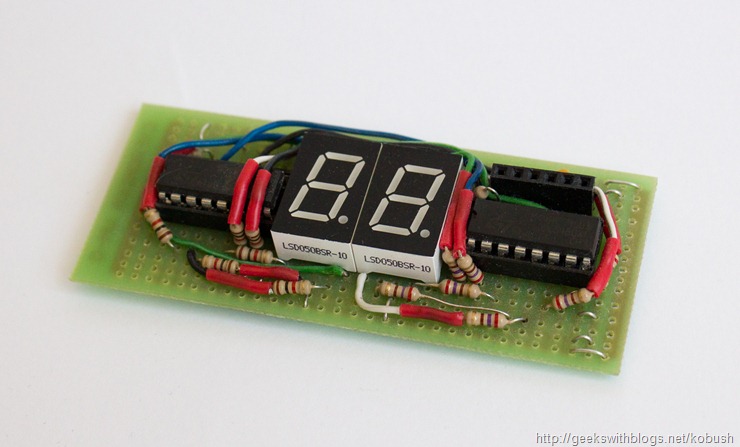
I’ve built a simple circuit with two 7-segment displays, so I’m also using two shift registers. You can build it on a breadboard as shown below, but I soldered it on a prototyping board to avoid messing with lots of wires. There is also an Arduino shield available called EZ-Expander Shield that you can use in your projects.
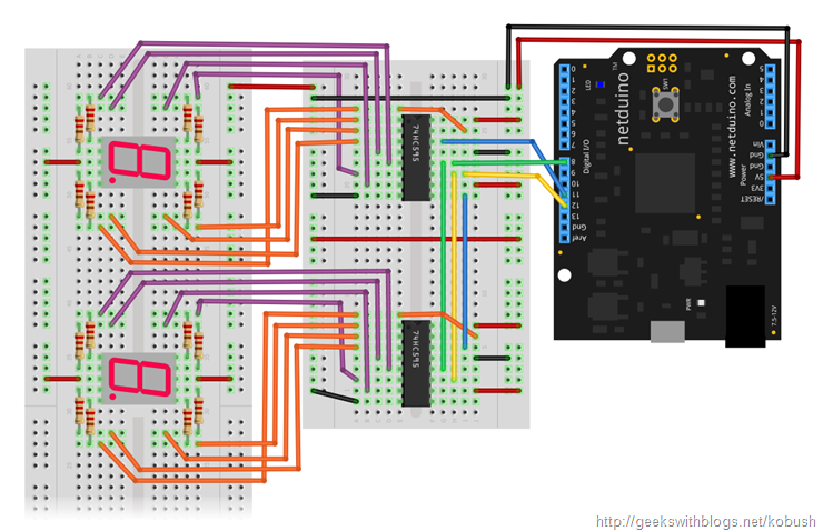
Here are the schematics of the circuit. I made it using Fritzing tool that I already presented here some time ago. The Fritzing file is included with the source code and I would like to thank Stanislav “CW2” Šimíček for creating a custom Netduino part for Fritzing:
A seven-segment display is made of 8 LEDs arranged in a matrix so that it can display decimal digits. It has 5 connectors on each side where central pin is used either as common ground or power (depending if you have a common cathode or anode version). Remaining pins are used to control individual segments. This diagram shows how the connections correspond to the LED segments:
You will notice that in my circuit I have common annode version. Also make sure to put 220Ohm resistor on other pins just like you do to protect regular LEDs. These pins are connected to the corresponding eight outputs of the shift register.
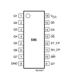
We need to connect only three pins to connect the shift register to netduino. In my circuit I connected these digital pins:
- pin 11 to serial data input pin (DS)
- pin 12 to shift register clock pin (SH_CP)
- pin 8 to storage register latch pin (ST_CP)
Only the first shift register is connected directly to netduino, because we can wire more shift registers in series (cascade). Latch and clock pins are wired directly to same input, but the data pin for second register must be connected to the serial out pin (Q7″) of first register. When we send the data signals to the first register after 8th bit it will overflow and forward these signals through the out pin to the 2nd register. You can find detailed explanation on how shift registers work in the article Controlling Your Festive Lights with the .NET Micro Framework at Coding4Fun.
You can download the source code for this project here. While it references Netduino assemblies it should work with little changes on other .NET Micro Framework devices like FEZ Domino, Meridian/P and others.
74HC595 and 7-segment display drivers
Now lets look at the code for controlling the shift register. I have separated this code to a class LED_74HC595_IOProvider. It implements simple interface ILED_IOProvider so it can be reused with different types of LED display components, and in the project you will find classes for 7-segment display and 10-segment bar graph.
Constructor of the LED_74HC595_IOProvider stores number of connected registers, and initializes output ports assigned to the corresponding shift register pins. Optionally you can set if data should be sent in MSB (most significant bit first) or LSB (least significant bit first) mode:
1 2 3 4 5 6 7 8 9 10 public LED_74HC595_IOProvider(short numRegisters,
                                                   Cpu.Pin latchPin,
                                                   Cpu.Pin clockPin,
                                                   Cpu.Pin dataPin,
                                                   BitOrder bitOrder) {
  _numRegisters = numRegisters;
  _bitOrder = bitOrder;

  _latchPort = new OutputPort(latchPin, false);
  _clockPort = new OutputPort(clockPin, false);
  _dataPort = new OutputPort(dataPin, false);
}
The Write method takes a buffer of bytes and sends them to the shift registers (each byte represents outputs of one shift register):
1 2 3 4 5 6 7 8 9 10 11 12 13 14 15 public void Write(params byte[] buffer) {
  // Ground latchPin and hold low for as long as you are transmitting
  _latchPort.Write(false);

  for (int i = 0; i < buffer.Length; i++) {
    ShiftOut(buffer[i]);
  }

  // Pulse the latch pin high to signal chip that it
  // no longer needs to listen for information
  _latchPort.Write(true);
  _latchPort.Write(false);
}
But all the heavy work is done inside the ShiftOut helper method that signals the bits in individual byte:
1 2 3 4 5 6 7 8 9 10 11 12 13 14 15 16 17 18 19 20 21 22 23 24 25 private void
ShiftOut(byte value) {
  // Lower Clock
  _clockPort.Write(false);

  byte mask;
  for (int i = 0; i < 8; i++) {
    if (_bitOrder == BitOrder.LSBFirst)
      mask = (byte)(1 << i);
    else
      mask = (byte)(1 << (7 - i));

    _dataPort.Write((value & mask) != 0);

    // Raise Clock
    _clockPort.Write(true);

    // Raise Data to prevent IO conflict
    _dataPort.Write(true);

    // Lower Clock
    _clockPort.Write(false);
  }
}
Now let’s look at the SevenSegmentDisplay class. The ShowValue method will display the provided decimal number. It uses a static lookup table to map digits to corresponding pattern of LED segments. I simply mapped the patterns from wikipedia. Currently only decimal digits are supported, but one extension to this class might be to allow using hexadecimal output formatting as well.
1 2 3 4 5 6 7 8 9 10 11 12 13 14 15 16 17 18 19 public void ShowValue(
    int value) {
  // Map digits to output patterns
  var buffer = new byte[_numDigits];
  for (int i = _numDigits - 1; i >= 0; i--) {
    byte digit = digits[value % 10];

    // Negate patten if its common anode display
    if (!_isCommonCathode)
      digit = (byte)(~digit);

    buffer[i] = digit;
    value = value / 10;
  }

  // Write output buffer
  _ledIoProvider.Write(buffer);
}
Example 1 – using potentiometer
For the simple test we will display a current reading of a potentiometer connected to one of analog inputs on netudiono. Don’t forget to connect Aref pin to 3.3V, otherwise the analog readings will be unknown. This is important fact to keep in mind because arudino has Aref internally connected by default.
This example is implemented in SevenSegmentLedWithPotentiometer class, and devices are setup in its constructor:
1 2 3 4 5 6 7 8 9 10 11 12 13 14 15 public SevenSegmentLedWithPotentiometer() {
  // Create IO provider for shift registers
  display_IO =
      new LED_74HC595_IOProvider(2, LED_Latch_Pin, LED_Clock_Pin, LED_Data_Pin,
                                 LED_74HC595_IOProvider.BitOrder.LSBFirst);

  // Create 7-segment display interface
  display = new SevenSegmentDisplay(2, display_IO, false);

  // Initialize analog input for potentiometer
  analogPort = new AnalogInput(Analog_Pin);

  // Set value range to display in 2 digits
  analogPort.SetRange(0, 99);
}
The main loop simple as well. Each iteration it reads the current value and sends it to the display:
1 2 3 4 5 6 7 8 9 10 11 12 13 14 public void Run() {
  while (true) {
    // Read analog value
    var value = analogPort.Read();

    // Show the value
    display.ShowValue(value);

    // Wait a little
    Thread.Sleep(100);
  }
}
Example 2 – using SHT15 temperature and humidity sensor
Now that we know that the display works fine lets use it to build a more interesting device, namely a digital temperature and humidity monitor. I’m going to use a Sensirion SHT15 sensor (SHT10, SHT11 and SHT15 works exactly the same and differ only by accuracy). You can buy a simple to use SHT15 breakout board from Sparkfun.The communication protocol for this sensor is bit tricky, but fortunately Elze Kool has already written a .NET Micro Framework SHT1x driver so I’m going to use it in my example.
This example is implemented in SevenSegmentLedWithTemperature class. Constructor adds initialization to the SHT1x sensor:
1 2 3 4 5 6 7 8 9 10 11 12 13 14 15 16 17 18 19 20 21 22 private void Setup() {
  // Set initial button state
  ButtonPressed = buttonPort.Read();

  // Soft-Reset the SHT11
  if (SHT1x.SoftReset()) {
    // Softreset returns True on error
    throw new Exception("Error while resetting SHT11");
  }

  // Set Temperature and Humidity to less acurate 12/8 bit
  if (SHT1x.WriteStatusRegister(SensirionSHT11.SHT11Settings.LessAcurate)) {
    // WriteRegister returns True on error
    throw new Exception("Error while writing status register SHT11");
  }

  // Run timer for measurments
  sensorTimer = new Timer(MeasureTemperature, null, 200, 500);
}
In addition we want to setup the onboard button, so that when is pressed display will show humidity instead of temperature. I’m using InterruptPort that will trigger an event each time button is pressed on released. This way I don’t have to poll the button state each time in the main loop:
1 2 3 4 5 private void HandleButtonInterrupt(uint data1, uint data2,
                                             DateTime time) {
  // Update button state
  ButtonPressed = (data2 != 0);
}
The temperature and humidity measurement takes a bit of time (maximum of 20/80/320 ms for 8/12/14bit resolution) and microcontroller has to wait for the measurement to complete. We don’t want to block the main thread waiting for this, so the obvious choice is to put the measurement in another thread. Here I’m using the Timer class to do measurements every 500 ms.
1 2 3 4 5 6 7 8 9 10 11 12 13 14 15 16 17 18 private void MeasureTemperature(
    object state) {
  Stopwatch sw = Stopwatch.StartNew();

  // Read Temperature with SHT11 VDD = +/- 3.5V and in Celcius
  var temperature =
      SHT1x.ReadTemperature(SensirionSHT11.SHT11VDD_Voltages.VDD_3_5V,
                            SensirionSHT11.SHT11TemperatureUnits.Celcius);
  Debug.Print("Temperature Celcius: " + temperature);

  // Read Humidity with SHT11 VDD = +/- 3.5V
  var humiditiy =
      SHT1x.ReadRelativeHumidity(SensirionSHT11.SHT11VDD_Voltages.VDD_3_5V);
  Debug.Print("Humiditiy in percent: " + Humidity);

  Debug.Print("Sensor measure time: " + sw.ElapsedMilliseconds);

  Temperature = temperature;
  Humidity = humiditiy;
}
After moving code for taking measurements and updating button state all that’s left in the main loop is simply updating the display when state changes (I added blinking LED to show how often the update is required):
1 2 3 4 5 6 7 8 9 10 11 12 13 14 15 16 17 18 19 20 21 22 private void Loop() {
  if (_needRefreshDisplay) {
    _needRefreshDisplay = false;

    statusLEDPort.Write(true);

    // Display current value
    if (ButtonPressed) {
      led.ShowValue((int)Math.Round(Temperature));
    } else {
      led.ShowValue((int)Math.Round(Humidity));
    }

    statusLEDPort.Write(false);
  }
}
VIDEO


